
This kit contains a complete offering of A/C compressor clutch hub pullers and installers for GM, Ford, Chrysler, Delphi, Sanden, Nippon, denso, DKS, and Zexel compressors.
It Includes a universal clutch holding tool and comes in a custom molded case.
The kit will remove the clutch hub from all the compressor listed. The kit also contains all the necessary tools to reinstall a clutch hub back onto the compressor.
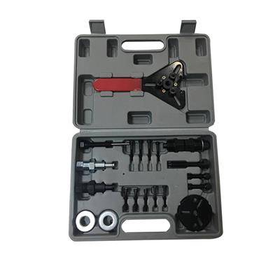
The kit contains 23 pieces in total.
1xThree eye round clutch plate arbor for Sanden, DKS, & Zexel
3 pieces of 5 mm – 8 Hex screws
3 pieces of 1/4″ – 20 Hex screws
2 pieces of 3/8″ – 16 Hex Screws
GM standard thread hub remover / installer
GM metric thread hub remover / installer
Chrysler, Nippon denso, & Ford course thread hub remover
DKS hub puller
Zexel hub puller Arbor installer
2 pieces of bearings
All of them are packed into molded carrying case.
These tools are Suitable for following air conditioning compressor clutches: – Sanden SD5, SD7, SD505, 507, 510, 575, 708, 709 – Zexel (Mitsubishi) – Denso 6P, 10P models for – Chrysler C171 – Ford FS6 – Hitachi MJ – Tecumseh HR 980 – Delphi / Harrison (GM) R4, A6, DA-6, HR-6, V5, DA6
REMOVING PROCEDURE:
- Remove shaft nut or retaining ring using the Universal Clutch Holding Tool.
- Thread removing tool onto hub. Make sure position center screw against the end of compressorshaft.
- Hold body of remover with wrench and turn center screw into remover body to removeclutch hub assembly.
INSTALLING PROCEDURE:
- Ensure frictional surface of clutch plate and rotor is clean.
- Align shaft key with shaft keyway and place clutch plate and hub assembly oncompressor shaft. (Do not drive or pound on clutch hub or shaft, as this may causeinternal damage to compressor.)
- Attach installing tool onto compressor shaft.(Body of installing tool should be backed off sufficiently to allow center screw tobe threaded fully onto end of compressor shaft.)
- Hold center screw with wrench and tighten hex portion of installer to press hub ontoshaft.
- Tighten body several turns until the air gap between the friction surfaces is .020 – .030”
- Remove installer and check for proper positioning of shaft key.
- Install shaft nut or retaining ring. (Refer to manufacturer specification for correcttorque).
- Spin pulley by hand to check for free operation.
WARNING
- Puller parts can break under stress!
- Be aware of hand positions.
- Wear safety glasses(user and bystanders)!
- Read and follow instructions.
- Do not heat pullers!
- Broken parts can cause injury!
- Do not over stress pullers!
- Avoid contact with refrigerant!
Lead time is 15-30 days and in most cases, we have stock and could ship to you immediately.
Gross weight is 5 kg and one 20 feet container could transport 3500 pieces.